A precision mold is not manufactured — it is built. Each one passes through a sequence of demanding, interdependent processes before it ever produces a single part. Depending on complexity, the journey from approved drawings to a production-ready tool takes 4 to 12 weeks — and for highly complex multi-cavity tools, up to 20 weeks. Every week in that timeline represents hours of skilled machining, careful inspection, and iterative refinement.
Here is what actually happens inside a precision mold manufacturing facility, step by step.
Step 1: 3D Design & Mold Flow Analysis
The process begins not on the shop floor, but at the workstation. Engineers use software such as SolidWorks or UG (NX) to develop the complete mold structure — cavity layout, runner system, cooling channel routing, and ejection mechanism design. Every component is modeled in 3D before any metal is touched.
Critically, this stage also includes mold flow simulation (via tools like Moldflow or Moldex3D) to analyze how the molten resin will fill the cavity, where weld lines will form, and whether the cooling system will deliver uniform temperature distribution. Problems identified at this stage cost virtually nothing to fix. The same problems discovered at T2 cost days of remachining.
For more on design principles that govern this stage, see our guide to mold design principles.
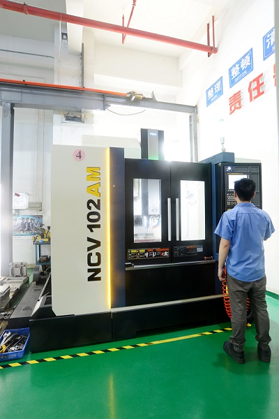
Step 2: CNC Machining
With the design validated, machining begins. High-speed CNC milling machines remove material from hardened or pre-hardened steel blocks to produce the cavity, core, and all structural mold plates. Typical CNC accuracy at this stage is ±0.01mm — tight enough for most structural features and runner geometry.
However, fine features below 0.1mm — such as connector pin holes, micro-ribs, or sharp internal corners — cannot be produced reliably by rotary cutting tools. These features require Wire EDM (slow-wire electrical discharge machining), which achieves accuracy of ±0.001mm by eroding material with a precisely controlled electrical discharge rather than a cutting edge. For demanding applications such as connector mold inserts, wire EDM is not optional — it is the only process that can hold the required tolerances.
Step 3: Heat Treatment
Most mold cavities and cores are machined in a pre-hardened or annealed state, then subjected to heat treatment to achieve the final hardness required for production. The standard process for hot work tool steels is:
- Austenitizing (high-temperature hardening) — The steel is heated to its transformation temperature, held for a calculated soak time, then rapidly quenched to lock in a hard martensitic microstructure.
- Tempering — The quenched steel is reheated to a lower temperature and held, relieving internal stresses and improving toughness without sacrificing hardness.
For H13 steel (equivalent to SKD61) — one of the most widely used grades in injection mold manufacturing — the result after quench and temper is a hardness of approximately 48–52 HRC. This hardness is what gives the mold its wear resistance across hundreds of thousands of production cycles. Using the right steel grade from the start is critical: see our VIKING mold inserts for an example of premium hot work steel selection in practice.
Step 4: Polishing
After heat treatment, cavity surfaces are polished to the specified surface finish. This is one of the most labor-intensive steps in the entire process — and one where shortcuts are immediately visible in the finished part.
Polishing progresses through a sequence of increasingly fine abrasives:
- Grinding stones and abrasive papers — Remove machining marks and establish a uniform surface
- Diamond paste on felt bobs — Progressively refine the surface through grades from coarse (9μm) to fine (1μm)
- Final mirror polishing — For optical-grade or Class A surface molds, the cavity is polished to Ra 0.01μm, a surface so flat and reflective that a clear human silhouette is visible in it
The required polish level is dictated by the part: a structural bracket may need only Ra 0.4μm, while a lens housing or cosmetic cover requires mirror-grade finish. Either way, the surface quality of the mold cavity is directly transferred to every part it produces — there is no downstream correction possible.
Step 5: Assembly & Fitting
With all machined and heat-treated components complete, the mold is assembled. Cavity inserts, core inserts, guide pillars, guide bushings, ejector pins, and return pins are all brought together and hand-fitted to ensure correct alignment and consistent clearances throughout.
Tolerances at this stage are extremely tight:
- Ejector pin-to-bore clearance: 0.02–0.05mm — too loose and flash forms on the part surface; too tight and the pin seizes during ejection
- Guide pillar-to-bushing fit: precision sliding fit, checked for smooth movement under load in all directions
- Insert-to-pocket fit: cavity and core inserts must seat fully and repeatably with no rocking or gap
Assembly is where the quality of every preceding step is tested. A cavity that machines perfectly but doesn’t seat squarely in its pocket will produce flash. A guide pillar with the wrong diameter will cause the mold to wear unevenly within the first thousand cycles. For precision mold components, dimensional consistency at this stage is non-negotiable.
Step 6: Trial Run (T1, T2, T3)
The assembled mold is mounted on an injection molding machine and run for the first time — the T1 trial. Parts are produced and inspected against the product drawing for:
- Dimensional accuracy (CMM measurement of critical features)
- Surface finish and appearance (sink marks, weld lines, short shots, flash)
- Mold action (smooth opening and closing, consistent ejection, no binding)
In practice, two to three trial rounds are typical before a mold is approved for production. T2 and T3 address issues identified in the previous trial — dimensional adjustments to the cavity, gate modifications, cooling optimization, or ejection system changes. Each round of modification is followed by another trial and inspection cycle.
The trial run stage is where all the upfront investment in design and simulation pays off — or reveals gaps. A mold that was thoroughly analyzed and carefully built typically clears T2 approval. A mold that skipped mold flow simulation or used incorrect steel often requires T3, T4, or in worst cases, a complete cavity replacement. For a broader perspective on the full lifecycle of a mold, see our 11-step mold manufacturing process guide.
What This Means for Buyers
Understanding these six stages helps explain why professional mold manufacturing takes the time it does — and why the cheapest quote is rarely the lowest-risk option. Every shortcut in machining, heat treatment, or polishing shows up in part quality or mold lifespan.
If you are evaluating tooling suppliers or planning a new mold project, we are happy to review your drawings and provide a detailed technical proposal. Send your 3D files (STEP format preferred) to info@moldtechpro.com.